
(Or Stuff that Every Ham Should Know)
by Mike Jahrig KG5P – KG5P@arrl.net
I had a discussion with a fellow ham recently. He has a nice modern rig but was unclear why the antenna impedance and feedline characteristic impedance must be matched to the transmitter impedance (almost always 50 ohms)
Since this is something that every ham should or must know, I believe it is important that I mention it. My fellow ham thought that if you used an antenna cut for 20 meters, then it would also work on 10 meters, just not as well.
The fact is, not only will it not work well, it would work really, really terribly and could damage the finals in your rig as a bonus.
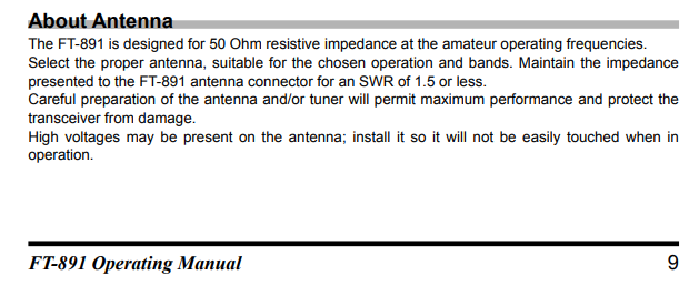
Above is a section of page 9 from my Yaesu FT-891 operating manual. Manual? You mean that paper thing with the writing on it? I always wondered what that was.
You can see they are pretty clear about matching an antenna to your rig giving no more than 1.5:1 SWR. You could stretch it maybe to 2:1 but any more than that, certainly at 3:1 and higher, you are getting into dangerous ground because you might let out the Magic Smoke. I’ve let out plenty of Magic Smoke in my life, but never, not even once, have I succeeded in putting it back in.
Consider the spreadsheet below. I have calculated forward and reflected power for all SWRs from 1.0:1 to 50:1. Note that at 1.5:1, only 4 percent of your power is reflected. Even at 2:1, only about 11% is reflected.
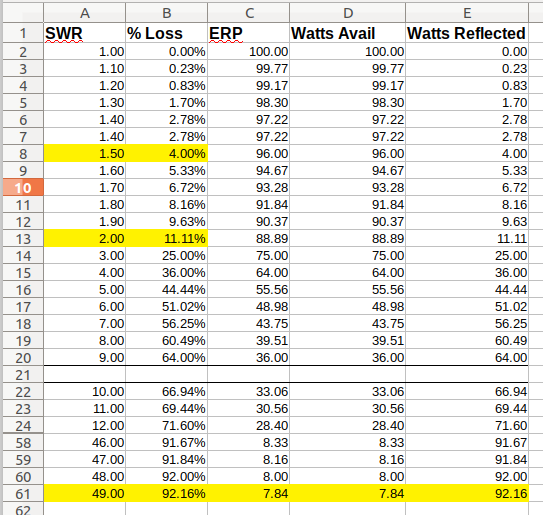
But look what happens at an SWR or 49:1. At that SWR, 92% is reflected back to your rig and only about 8% goes out over the air. Actually, it’s even worse than that because we haven’t even considered losses like heating if you are use a coax feedline.
So where does that 92% go that is not going into the ozone as RF? Well, magic smoke, maybe. It’s being reflected back into your rig trying to burn it up like a short circuit. Fortunately, many of the newer rigs can detect a large mismatch and start shutting down by reducing power long before, but I don’t know what rig you have so it may not. At any rate you would do well to not press your luck
So what’s the deal with an SWR of 49:1? It turn out 49 is the SWR presented to my friend’s rig when he tried to load a 20m antenna on 10m.
Think about it for a moment. If the 20m antenna is a resonant dipole, to be resonant it must be 2x 1/4 meter legs connected together with a feedline. Each leg of the dipole is then 1/4 wave long.
Antennas and radios get along really fine in these conditions. It turns out that you are feeding the center point of the dipole at a current loop which means that since current and voltage are 90 degrees out of phase. Thus, you are also feeding it at a voltage node. This is what you want. Since Z = V/I, the voltage is low while the current is high. Ohm’s law tells us that a very low voltage divided by a high current gives us a low Z. (Ideally 50 ohms)
Now my friend had this just backwards. His 1/2 wave dipole with 2 1/4 wave legs on 20m works out be be a full wave dipole with 2x 1/2 wave legs on 10m. There is no such thing as a naturally resonant full wave dipole. By naturally, I mean without additional components added. You can make anything resonant if you have a stiff enough tuner. But in reality, you are not making anything resonant. You are just fooling the transmitter into thinking it is.
This is just what your transmitter doesn’t like. It was designed at the factory to like 50 ohms. What he is doing by using a 20m dipole on 10m is the voltage and current nodes and loops are reversed. Not only is this bad, it’s so bad that it can’t be any worse. The ultimate in bad. As bad as having no antenna at all. If this could work, all the antenna manufacturers would be put out of business.
So instead of low voltage/high current = 50 ohms, he has high voltage/low current = something much much higher than 50 ohms. I calculate about 2450 ohms. I won’t go through the The Math (yes, there is math) but you can also empirically determine it with an antenna analyzer.
Whichever way you do it, it works out that his 50 ohm transmitter is looking into 2450 ohm antenna giving about a 49:1 mismatch or SWR of49:1. Is that Magic Smoke I smell?
I will explain in more detail what’s really going on. Consider first a half wave dipole cut for 20 meters and loaded at 14 mhz.
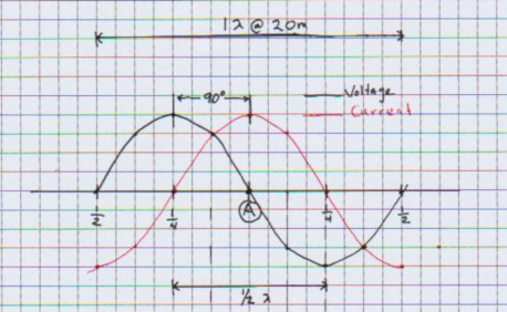
Look at point A. Let’s say this is the feedpoint and it is half way (1/4 wave) between each end point of the antenna. (Each end being 1/4 wave each side of pt.A.) That’s why they are called half wave dipoles. Note the voltage waveform (black) at this point. It is at a “voltage node” and has a zero value at this point.
Now look at the current waveform (red.) Note that it happens to lag the voltage by 90 degrees (remember Eli the Iceman) and is maximum (high, pick your own number) at that point.
Ohm’s law tells us the impedance at that point: Z = V/I or Z = 0/1 = zero ohms. That is what we want and this dipole is loaded correctly; we want to present a low impedance to the transmitter.
Yes, you say. But the transmitter wants 50 ohms, Why is it zero here?
Well, there is more to the story so I will digress for a few seconds. The Z in this case is pure reactance. I am ignoring the radiation resistance which you must also consider when calculating the actual impedance. So, in reality, the actual impedance due to the characteristics of the physical conductor is not zero ohms, but something else, maybe 50 ohms (we hope.) In any case, lets just get back to Z = X and set R = 0 for this discussion.
Now lets see what happens when we feed the same 20 meter dipole at 10 meters. Consider the graph below:
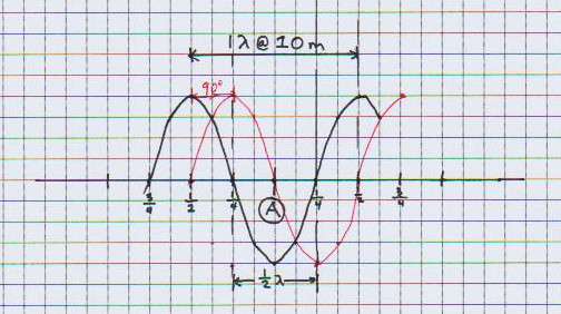
First, note the antenna is the same length as above. It is 1/2 wave at 20 meters but since we are feeding the same physical antenna with a 10 meter signal, it is a full wave long at 10 meters. And each leg is a 1/2 wave long instead of 1/4 wave You just turned it into a full-wave dipole. That is bad and here’s why.
Look at point A. Pt A is now at a voltage loop and the current is at the current null. Also look at the quarter wave points. The nulls and loops are reversed. That is what happens at any quarter wave point. But now since the voltage at point A is now at max and the current is zero, it is backwards from what we had above when we were supplying a 20 meter signal. Ohms law now gives Z = (high)/0. I would like to say that high voltage/zero = infinite Z. That is saying that you are terminating your transmitter with an open circuit and it will think you have no antenna attached and all the power from your transmitter will have no place to go, except back into itself. This is the same reason that you will burn up your microwave if you don’t put something inside before you will turn it on; it will produce an infinitely high SWR and destroy the magnetron.
But the mathematicians would have a big problem with that statement A mathematician would tell you that there is no solution when you divide by zero. They would say that the answer is “undefined” because infinity is not a number.
I’m not a mathematician. That job is way above my pay grade. Mathematics are just stuff that engineers keep in their toolboxes to solve real-world problems. So if you want to know more about dividing by zero, you will have to consult your friendly local math Ph.D.
But I can say this: If you could divide by zero and if the math worked, you could do all kinds of crazy things like prove that 1 equals 2.
So I just say the what happens at the feed point of a half-wave 20 meter antenna when feeding it a 10 meter RF signal is that you will have an infinitely SWR. That is what the SWR meter would say because the reflected power would be 100%, all of which would be trying to melt down your rig.
So the takeaway here is this: Don’t attach your transmitter to a current node/voltage loop unless you need a new doorstop. Because after the magic smoke gets out, that’s what you will have
This is true with feeding any half-wave dipole with an even multiple of 1/4 wave of the frequency it was cut for, like feeding a 40m dipole at 20m. It is also why you can feed a dipole cut for 40m (7 mhz) with 15 meter (21 mhz) signal because 15m is an odd multiple (3x) of 1/4 wave.
Receiving is reciprocal. That is why the fox hunt chasers can listen to the fox at 70cm because it is an odd multiple of 1/4 wave (3x) of 2 meters. The antennas work just fine.
One final word. I haven’t said anything about transmission lines. Depending on the type and length transmission line you are using, everything I said above above may or may not be a consideration. But that is an entirely different topic.