By Mike Jahrig KG5P
(Part 2 of a series)
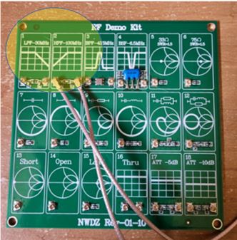
This month I will continue my discussion of the NanoVNA. One useful accessory I have found is a RF Demo Kit that I bought off the internet from Banggood or somewhere for about 12 bucks. This device contains a lot of test components that you can experiment with while exploring the functions of your Nano VNA. Note the 30 MHz low-pass filter (LPF ) and the 100 MHz high-pass (HPF) filters in the upper left.
Today we start our investigation of common filters found in all amateur radio equipment, specifically low-pass and high-pass filters.
Low Pass Filters
In the Heathkit days, up until the mid 80s, you probably assembled your own low-pass filter if you built your own Heathkit. Current factory built radios also have them although they may not be obvious to the operator.
Let’s refresh you on the function of a low pass filter. The simplest form is a resistor-capacitor coupling circuit. This filter allows the lower frequency components of the voltage applied to it to develop across the resistor, while the high frequency components are attenuated at the output. See the diagram below:
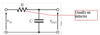
You can see here that AC current flowing from the input terminal flows to the output terminal through the resistor. But due to the properties of capacitive reactance, some of this current is shunted to ground and never makes it to the output.
From your General Class studies, you will recall Xc = 1 / 2 (pi) f C, where X, reactance, remember is the opposition to an AC current. Thus you can see here that if f (frequency) increases, then Xc decreases. Since this decrease in current opposition on the leg of the filter connected to ground is through the capacitor, more current is shunted to ground and thus less is routed to the output. In essence, this functions exactly as a simple voltage divider. The higher the frequency, the more current is shunted to ground. Therefore, higher frequencies are greatly reduced in the output, and we have a low-pass filter; lower frequencies are passed to the output, and higher frequencies are attenuated. The resistor, on the other hand, does not attenuate AC by frequency.
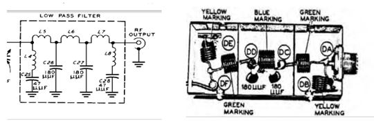
Although a resistor may be used in a low-pass or high-pass filter, typically an inductor is used. This inductor can be in the form of a coil, but these days, a toroid inductor is usually used. To the left is the low pass filter that I actually built as a Novice ham for a DX-60 transmitter. It was installed in a nice little shielded metal box.
The main function of the LPF is to keep harmonics and other spurious signals from leaking into frequencies higher than for what the transmitter was intended to emit (like the old analog over-the-air TV broadcast frequencies.)
The cutoff point in filters is customarily defined as when the frequency has been attenuated by 3dB or as we like to say, down 3dB or minus 3dB. Why 3dB? Recall from your General Class studies what dBs are: They are simply a way to represent a ratio between 2 power levels (or voltage or current levels). So when we say “down 3dB” for a filter we mean the frequency where the power output of the DUT (Device Under Test) has been reduced to ½ of the input. Thus, another way of saying the same thing is that the cut-off frequency is the half-power point.
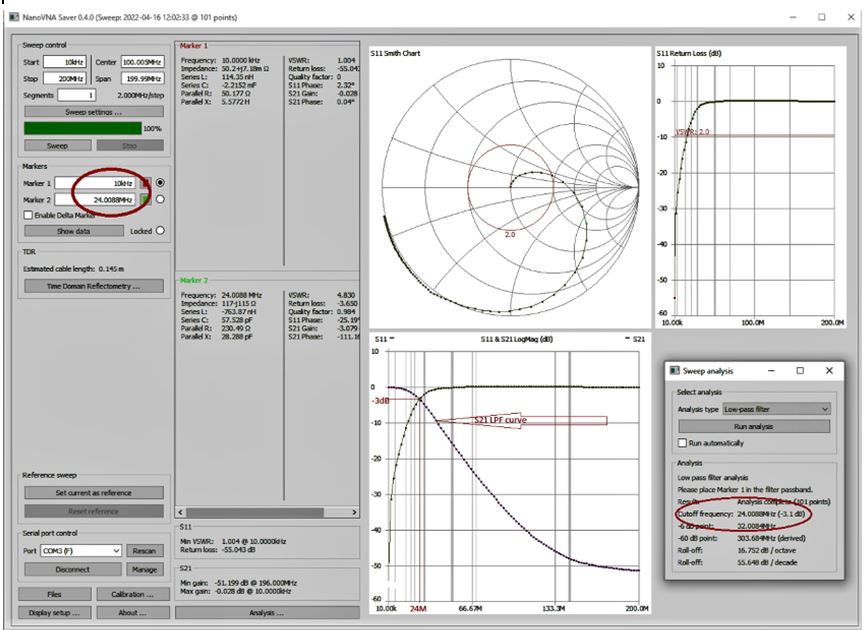
So now let’s look at how this looks on the Nano VNA.
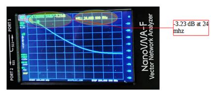
The Nano tells us that the -3dB point actually occurs around 24 MHz, instead of 30 as advertised. That tells us that whatever power we input at a lower frequency, we approach -3.1 dB or ½ that power out of the DUT as the input frequency approaches 24 MHz.
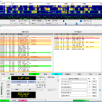
On the NanoVNA saver app screen on Windows, look at the blue S21 trace. It shows the cutoff characteristic of the LP filter and the -3 dB point occurs around 24.01 MHz. Also look at the sweep analysis on the lower right. Assuming that no attenuation occurs at the 0 dB point, it tells us that -3dB attenuation occurs at the cutoff frequency of 24.010 MHz for this particular LP filter. Below is a screen print of the NanoVNA-saver app. It displays the same information as the Nano screen, but only 101 data points compared with 301 for my Nano. Also the Nano displays the exact frequency and logmag values where you have to eyeball them on the NanoVNA-saver app. The app also tries to calculate the ½ power point or cutoff which you can see in the lower right hand corner. It thinks it’s actually 24 mhz, not 30. (Figure 6.) I believe 24 is correct. See how it passes frequencies below 24 MHz and attenuates those above. Figure 6. That is a low-pass filter.
High Pass Filters
Now let’s look at the high-pass filter as displayed on the Nano VNA. The HP filter works exactly the same as the LP filter, except in reverse. As the name implies, it passes those frequencies above the 3dB cutoff while attenuating those below.
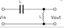
As with LP filters, these may be constructed various ways, with resistors, capacitors, or inductors, or typically today, op-amps or other active circuits. A simple HP filter diagram using passive components is shown to the left.
Recall the formula for inductive reactance: Xl = 2 (pi) f L
This tells us that the reactance X increases with frequency. This opposition to AC current increases with frequency through the shunt inductor and thus less current is shunted to ground. This with the series capacitor allows more power to reach the output of the device at frequencies above the ½ power point. As with the low pass filter, the resistor may be replaced with an inductor or capacitor. The resistor would work, but a capacitor and inductor gives a steeper rolloff curve.
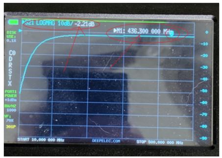
Here’s what a 100 mhz HP filter looks like on a Nano VNA. Look at the marker at the right end of the scale. It appears that about 2.21 dB of attenuation at 436 mhz is built into this filter. It seems to be flat all the way across above the cutoff point. I’m not sure why this happens. We will just make it the relative 0dB point to start. So to find the ½ power cutoff point, let’s move it down another 3 dB by adding it to the existing 2.21 dB power loss giving about 5.21 dB. That should be the true 3 dB cutoff.
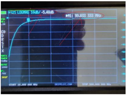
Now let’s move Marker 1 to about the 5.21 calculated cutoff point. You can see that marker M1 tells us it occurs at 99.8 mhz at -5.48 dB, close enough to -5.21 that we calculated. Marker M1 is near the 100 MHz cutoff frequency this filter claims to have.
Lastly, back in the golden days of TV, we hams had to know about both these filters. Before cable digital TV replaced Over The Air analog TV, the VHF low bands were just above the ham HF bands. Channels 2 – 6 used 54 to 88 MHz. So if you had any harmonics or out-of-band emission from your transmitter above 30 MHz, it could possibly cause interference (TVI) in the adjacent TV channels. The FCC was empowered to issue “pink tickets” and impose “quiet hours” at certain times of the day to offending hams. A possible solution, other than going QRT, was to install a LPF on the transmitter or a HPF on the TV, or both.
This concludes my discussion of low-pass and high-pass filters using the NanoVNA. Fortunately we don’t have to think about LP and HP filters much anymore with today’s well designed factory-built transmitters and satellite and fiber TV delivery.
Next time we will investigate bandpass and bandstop (notch) filters on the Nano VNA. These are found in most modern radios on the front panel and are adjustable by the operator. They are used to remove QRM and adjacent annoying signals like heterodynes and birdies. You probably have them on yours.
Stay tuned to this station.
73 de KG5P